Description of design
The pottery wheel design can be conceptualized as being a unit made of four components: the throwing surface, the wheel shaft, the kickwheel, and the support table. This explanation will discuss the various material choices made for each of the components and the motivations behind those choices.
The throwing surface is the flat spinning disk at the top of the throwing wheel on top of which the pottery will be thrown. The main structural requirement for this component is that it must be rigid enough to be supported only from the center and still support a load distributed across its surface (i.e. a pot and the potter’s hands) without bending. This component also sees a lot of human interaction, so the user requirements for this component are that it must not be dangerous for a human hand to near it while it is spinning at a high velocity and that is must be able to function as a good surface on which to throw clay. To satisfy the structural requirement, we chose to build the bottom of the surface out of an 8’’ by 8 ‘’ plywood square. This would be sufficiently rigid to support the loads induced by the pottery and the potter. However, even a well-sanded plywood surface could potentially give a potter splinters while it is spinning at high velocity, and so our design includes a thin acrylic layer (12’’ diameter circle) that will be fastened concentrically to the square. While making the device more comfortable for the potter, the acrylic also has the potential to be lightly scored to grip the pottery better.
The wheel shaft is the pole which will connect the throwing surface to the kickwheel. The main constraint on the shaft is that it must not buckle (i.e. fail by bending) under the weight of the pottery and the force of the potter’s hands. If this were to occur, the pottery wheel would not spin properly around the axis of the shaft. For this reason, we chose a steel pipe as our shaft material. The calculations demonstrate that the steel shaft is more than capable of withstanding the necessary loads without buckling, and so it is an appropriate choice. The shaft also must be able to provide moments (i.e. sustain reaction forces to the rotational motion of the wheel potter against the potters hands), but the shaft will be connected to the kickwheel and surface with flange mounts so this will be assumed to not be a problem.
The kickwheel is the heavy wheel at the base of the structure which will serve two functions. It will be the surface on which the potter kicks, and it will act as a flywheel and store kinetic energy so the apparatus will continue to spin even if it is not being kicked. To fulfill these functions, a very heavy, symmetrical disk is necessary. A barbell weight of approximately 20 kg was chosen because it meets these requirements and is an easy to find product. Barbells weights can also be obtained with rubber coatings, which will provide friction against the shoe or foot of a potter and ease the kicking process. The kickwheel itself will be supported by a thrust bearing, which by itself should allow the assembly to spin with negligible friction.
Finally, the support table will keep the wheel assembly upright when it is not spinning or spinning at a low angular velocity. The surface of this table is not meant to be load bearing; the table is only to keep the shaft of the assembly upright when the angular momentum of the kickwheel isn’t sufficient to prevent tipping. Therefore, the assembly will be a plywood structure with hole in the center of the table surface that is slightly larger than the shaft, so that the shaft may spin freely. Teflon tape can be used to line the interior of the hole so that friction can be minimized between the table and the shaft.
Buckling Load Calculation
Assumptions
- Euler buckling is the failure mechanism for the drive shaft.
- The shaft is modeled as a column with one fixed end and one free end
Calculations
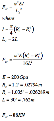
Conclusions
Although this is theoretically the buckling load of the conduit, the flange fixtures used to mount it to the bearing would fail far before then. The assumption of a full moment connection at the base (which allows us to calculate the Euler buckling force in the first place) is in fact false and used to simply compare the theoretical strength of the conduit to the strength of other system components. In conclusion, global buckling in the shaft will not be the failure point of the system. Rather, the large moments about the flange at the base and the thrust bearing created by the long moment arm of the shaft would be likely points of failure. The supporting table is used to constrain the displacement of the end of the shaft and therefore limit the moments transferred to the base components.
Inertia Calculation
Assumptions
- The flywheel is assumed to be a disk of uniform mass distribution
- The coefficient of friction is independent of time
- The inertia of the clay mass and top are negligible compare to the flywheel
- The rotation of the table is considered to become ineffective at ½ the initial angular velocity
- The coefficient of friction used is that of brick against wet clay (no values for skin against clay could be obtained
Calculations
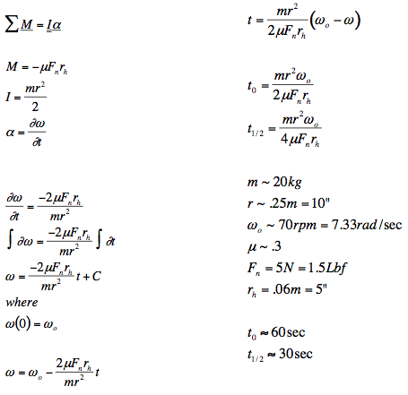
Conclusions
The times found are conservative estimates since the coefficient of friction for brick against wet clay is obviously larger than that of skin against wet clay due to a qualitatively greater surface roughness. Additionally, the estimate of the value of moment of inertia is conservative since on most weights, the mass is distributed further away from the center of mass thus raising its moment of inertia. The value chosen for the RPM of the kickwheel is an estimate based on the RPM of low power electric kickwheels designed to mimic manually driven kickwheels.
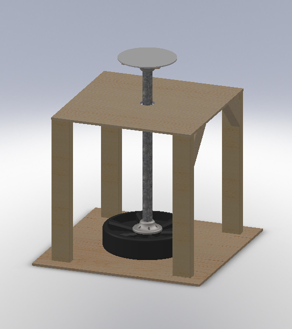
CAD Model
Pottery Writeup
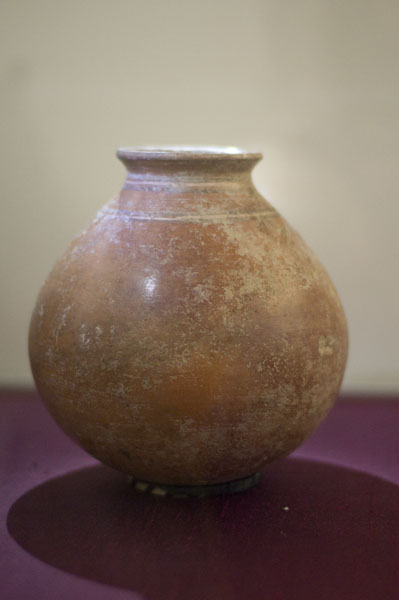
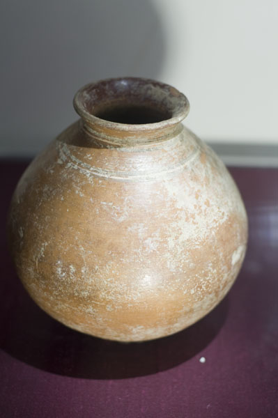
Nick's pot is a coil built pot made of Malone Red Clay with sand added as temper.
Max's pot is wheel thrown, slightly increased thickness, Malone Red Clay with no added temper.
Jeremy's pot is coil built, matching the original form but made from Grey Stoneware Clay, with much added sand as temper.
The narrow neck and wide body of the vessel will increase the difficulty of producing such a thin-walled wheel-thrown replica. Maintaining even wall thickness and symmetric construction will be difficult when using coil-building techniques since very thin coils are required. The addition of temper will further complicate the coil-building process since it will decrease the plasticity of the clay and may lead to crack formation in very thin coils. The burnished exterior of the original vessel will be difficult to replicate due to the relatively thin-walled construction. We hope to improve the mechanical properties of the vessel by increasing wall thickness and decreasing the potential for crack formation by forming the piece on a pottery wheel. This construction technique will result in a homogeneous clay body that lacks the areas of weak adhesion found between coils on coil-built vessels.
We also hope to test the ability of the vessel to better withstand uneven heating and firing by incorporating sand temper into the clay body. The sand will decrease the plasticity of the clay while providing increased tensile strength and enhanced resistance to fracture by gaseous expansion during firing. Since the sand is composed primarily of Quartz, it will have nearly the same coefficient of thermal expansion as the clay body, thus minimizing the addition of thermal stresses during heating and firing caused by material strain inconsistencies.
In addition, including temper in different iterations of this pot recreation allows for greater mechanical strength by decreasing the potential for crack propagation. For any given crack of a specific size and geometry that appears in a ceramic vessel, there is some critical stress that exists, beyond which any applied stress will cause the crack to propagate across the specimen, and then failure will likely ensue. However, the presence of tempering particles in the clay acts as a barrier to this crack propagation, and ultimately raises the critical strength required for crack propagation. It would be interesting to be able to perform some mechanical testing (for things like fracture toughness or hardness) on these and other items the class produces, to get a basic rough idea about how much of an effect the tempers we are using have on the mechanical behaviors of the objects.
The radius of the pot is approximately six inches at the widest point. It is nearly round, very thin walled, with a two inch diameter opening at the top. Finally, the lip curves outwards to approximately two and a half inches at the very top. The base is around two inches in diameter.